References
1. PrisMax Operator’s Manual. 2024; AW8061.
2. Vantive Internal Documentation, Quantitative Assessment of User Needs for Clinical Solutions. 2020.
3. Broman M, Bell M, Joannes-Boyau O, et al. The Novel PrisMax Continous Renal Replacement Therapy System in a Multinational, Multicentre Pilot Setting. Blood Purif. 2018; 46:220-227.
4. ECRI Institute. Top 10 Health Technology Hazards For 2013. Health Devices.
5. Christensen M, Dodds A, Sauer J, et al. Alarm Setting For The Critically Ill Patient: A Descriptive Pilot Survey of Nurses’ Perceptions of Current Practice in an Australian Regional Critical Care Unit. Intensive Crit Care Nurs. 2014; 30:204-210.
6. Sendelbach S. Alarm Fatigue. Nurs Clin North Am. 2012; 47:375-382.
7. TherMax Operator’s Manual. 2024; AW7006.
8. Vantive Internal Documentation. PrisMax Limited Controlled Distribution Report. 2017.
9. Vantive Internal Documentation. Acute Therapies Global Research Study, Final report on quantitative and qualitative findings. 2019
What is the communication unit?
The communication unit consists of the touch screen display and the machine alarm status light. It is used to input and receive all system information.
- THE STATUS LIGHTS
- THE SCANNER
- THE USER INTERFACE

The scanner
The scanner is located at the top of the machine.
It is used to scan the disposable sets during set-up mode and can scan the patient ID. It pre-populates parameters and capabilities via barcode/QR code.

The User Interface
Touch screen display with intuitive graphics and icons providing step-by-step instructions for operating the PrisMax machine.
The touch screen is built up around 5 sections:
- TOOLBAR
Includes various buttons to access therapy data and prescription information - FLOW RATES
Shows each flow rate with the ability to change the flow rates - PRESSURE BARS
Indicates current operating pressure measurement, operating range, and alarm limits - EFFLUENT AND PFR DOSING PARAMETERS
Shows the prescription value and what has been delivered - PRESSURE HISTORY & SET LIFE
Displays the filter drop pressure and the TMP/TMPa (as applicable) pressure over the last 6 hours of treatment and current set life (hr:min)
Continue the walkthrough explaining the Blood Flow Management on the PrisMax System.

What is Blood Flow Management?
The PrisMax System’s Blood Flow Management section consists of pumps, pressure sensors, and a deaeration chamber, all located in the middle section of the machine.
- ATTACH CARTRIDGE & LOAD SETS
- BLOOD PUMP
- SOLUTION PUMPS
- MONITORING SYSTEM
- PINCH VALVES
- PRESSURE SENSORS
- SYRINGE PUMP
- BLOOD WARMER

Attach cartridge & load sets
- CARTRIDGE HOLDER
Holds the cartridge in the disposable set. Fits with all sets - LINE HOLDER
Designed to hold /control lines from the disposable sets

Blood pump
Pumps blood through the blood flow path of the disposable set.
Runs in mL/minute.
Capable of running 0-450 mL/min. based on therapy setting and disposable set in use.
Solution pumps
Controls solution flow rates from the scales - directs solutions into the filter and the bloodstream.
Runs in mL/hour.
- EFFLUENT PUMP
Pumps ultrafiltrate/dialysate. It controls the removal of solution from the filter as well as patient ultrafiltrate
Color-coded YELLOW to coordinate with the disposable set/Scales - PRE-BLOOD PUMP (PBP)
The solution from the corresponding scale will go in before the BLOOD PUMP and the FILTER. (Pumps solution into the blood access line at a location after patient blood enters the line and before the blood pump)
Color-coded WHITE to coordinate with the disposable set/Scales - DIALYSATE PUMP / REPLACEMENT PUMP 2
Running CVVHD + CVVHDF:
Pumps dialysate solution into the fluid compartment of the filter
Running CVVH: serves as REPLACEMENT 2 (Solution into blood flow)
Color-coded GREEN to coordinate with the disposable set/Scales - REPLACEMENT PUMP
Infuses replacement solution into the flow path. Depending on the prescribed therapy, the pump infuses solution into the flow path pre-filter, post-filter, or both. This is set by a pinch valve
Monitoring system
- DEAERATION CHAMBER HOLDER
Some actions during treatment can add a small amount of air into the set and change the fluid level in the deaeration chamber. The machine uses the Liquid Level Sensor (LLS) in the chamber holder to check the fluid and adjust or warn appropriately. - AIR BUBBLE DETECTOR (ABD)
Detects bubbles and micro-bubbles. If detected it may generate a red alarm (a safety feature) - Air in Blood - and engage the RETURN LINE CLAMP (see point #3).
Serves as a safety control for the Deaeration Chamber function - RETURN LINE CLAMP
The return line clamp closes to prevent blood or air from passing to the patient. The clamp automatically closes when power is off, during some self-tests, or in case of a possible patient safety hazard. Installing tubing under the clamp engages a tubing detection switch. - BLOOD LEAK DETECTOR (BLD)
Houses the effluent line - a sensor makes it possible to check for/detect blood in the effluent line. Problems with the therapy or the filter may result in blood in the effluent line - DISCHARGER RING
Holds the effluent line of the disposables - designed to remove static electricity generated in the PrisMax system and ground it to prevent possible interference with other (ICU) equipment

Pinch Valves (Upper & Lower)
Controls solution flows based on interaction and end-user choice of therapy and replacement modalities.

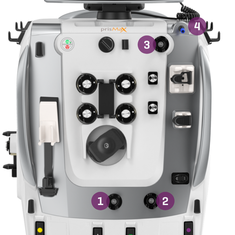
Pressure sensors
Monitors pressure within the system when blood and fluids are moved through the system.
- ACCESS PRESSURE SENSOR
Monitors the access line pressure, how much pressure it takes to pull blood through the vascular access device, from the patient, and into the filter - FILTER PRESSURE SENSOR
Monitors the pressure of the blood entering the filter. It works with the Return Pressure Port (#4), which monitors filter return pressure.
Together, they calculate the filter pressure drop and how the filter is running - EFFLUENT PRESSURE SENSOR
Monitors the effluent line pressure and the amount of pressure needed to get the effluent flow across the membrane from inside the filter to the effluent bag.
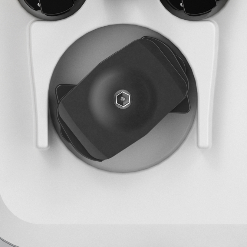
Helps calculate transmembrane pressure - RETURN PRESSURE PORT
Connects to the deaeration chamber pressure monitor line on the disposable set. A fluid barrier at the distal end of the monitor line protects the return pressure sensor from accidental blood entry. Enables non-invasive monitoring of return line pressure
Syringe pump/holder
It can hold either 20 mL. or 50 mL. syringe (depending on configuration).
Solution-filled syringe used for:
- Heparin: in Systemic Anticoagulation mode
- Calcium (Ca): using Citrate-Calcium software*
*Software not approved for use in the US.

The TherMax blood warmer
An intelligent, high-efficiency blood-warming device with low extracorporeal blood volume. Once the prescription temperature is entered, the operator does not need to make further management or power adjustments to maintain it.
Warms the blood to the set temperature. Blood temperature between 35,0 C and 38,0 C.
Lights and Icons on top for operation status, communicating directly with the PrisMax machine.
Connected to the PrisMax system by VGA cable on the Back Panel (middle socket).
The TherMax disposable bag is designed to allow maximum heat transfer from the warmer. It has inlet and outlet connectors to connect in line with the blood filter set.
Continue the walkthrough explaining the Fluid Management on the PrisMax System.

What is Fluid Management System?
Scales hold solution bags to be used. Scale software monitors the weight of each fluid bag to precisely control solution flow rates and patient fluid removal (PFR).
- EFFLUENT SCALE
- PRE-BLOOD PUMP
- DIALYSATE SCALE
- REPLACEMENT SCALE
- AUTO-EFFLUENT (AE) ACCESSORY
- DRIP TRAY
Color coding, icons, and geometrical shapes correspond to specific pumps and disposable sets. Corresponding light for each scale to indicate status.

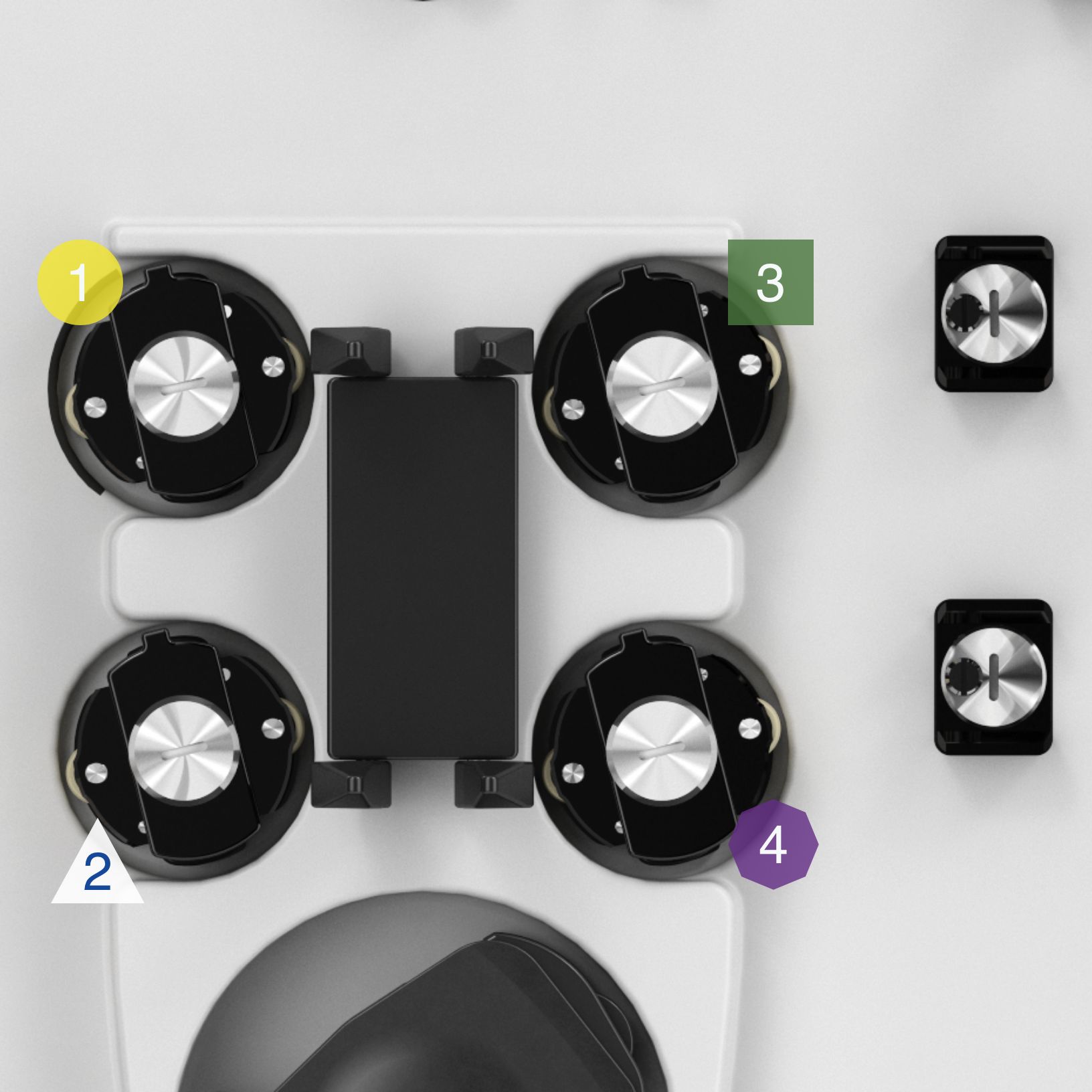
Effluent scale
Color-coded: YELLOW circle
The effluent scale monitors the volume of fluid removed from the patient during treatment. This scale ensures that the effluent pump maintains the required flow rate, calculated by the plasma loss rate and replacement fluid rate.

Pre-blood pump scale (PBP)
Color-coded: WHITE triangle
The PBP scale monitors the volume of fluids infused before the blood enters the filter. This scale plays a critical role in therapies that require pre-filter fluid infusion, such as anticoagulants in regional citrate anticoagulation. The PBP scale ensures that the appropriate amount of fluid is infused, preventing clotting and maintaining system functionality.
*not approved for use in some countries

Dialysate scale
Color-coded: GREEN square
This scale is responsible for tracking the dialysate solution's weight, ensuring the correct amount of fluid is used during dialysis. While not utilized in TPE, the dialysis scale plays a crucial role in Continuous Renal Replacement Therapy (CRRT) by managing the balance between the removal of waste products and fluid administration.

Replacement scale
Color-coded: PURPLE octagon
The replacement scale is essential for managing the weight and volume of replacement fluids administered to the patient. This scale adjusts for various container sizes, allowing for precise fluid management down to as little as 10 mL increments. The system ensures that fluid replacement is balanced against effluent removal to maintain patient stability.

Drip Tray
Integrated in the base of PrisMax is a well and a sensor to help detect leaking fluids from the solution bags or fluid circuits.
An alarm goes off if leaked fluid accumulates past a fixed limit.

T1238 – Access extremely negative
Alarm definition
Self-clearing alarm indicating that the access pressure has reached the default threshold of -250 mmHg.
Possible causes
- Patient movements, such as coughing or suctioning
- Clamped or kinked access line
- Quality of vascular access
- Blockage or clotting in the catheter
Other causes/Considerations
- Excessively high blood flow rate
- Type of set in use
- Blood characteristics
Operators Instruction
The PrisMax will try to self-clear – and if possible, clear the alarm.
If unable to self-correct it will turn into a T0775.
See T0775 for further instructions.

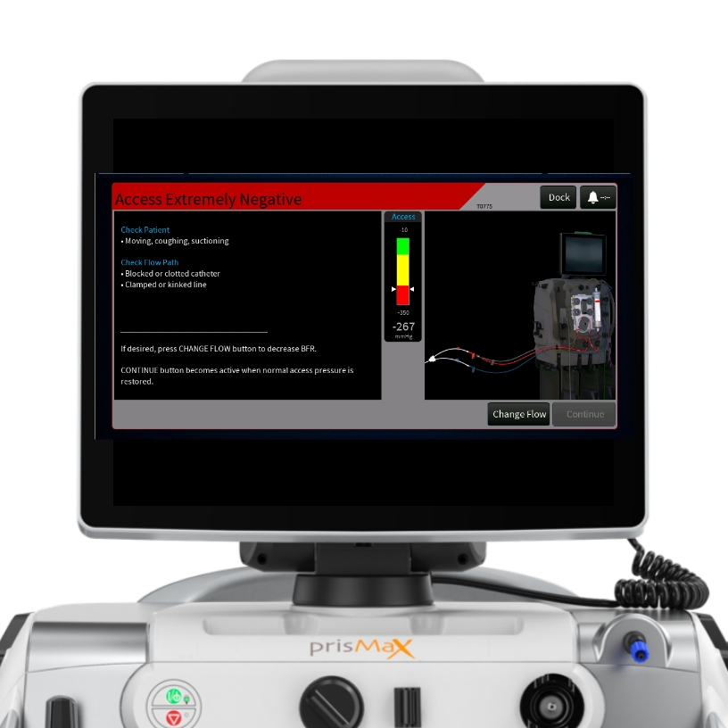
T0775 – Access extremely negative
Alarm definition
This alarm is a follow-on alarm to the T1238, indicating that a self-clear operation could not be completed, and that the access pressure has been maintained above the default threshold of -250 mmHg.
Possible causes
- Patient movements, such as coughing or suctioning
- Clamped or kinked access line
- Quality of vascular access
- Blockage or clotting in the catheter
Other causes/Considerations
- Excessively high blood flow rate
- Type of set in use
- Blood characteristics
Operators Instruction
- Adjust Blood Flow Rate: If necessary, decrease the blood flow rate
- Asses catheter:
- Follow hospital protocols to flush or reposition the catheter if it is suspected to be blocked or clotted
- Ensure adequate cather size for prescribed blood flow rate - Correct Kinks or Clamps
- Make sure access line is securely connected to catheter/blood source
Once the issue is fixed, the ‘Continue’ button can be pushed.
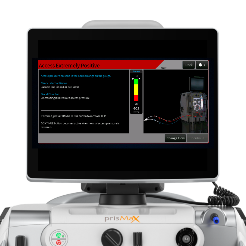
T1237 - Access extremely positive
Alarm definition
This alarm indicates that the access pressure has exceeded the threshold of + 450 mmHg.
Possible causes
- Blood Flow Rate too low
- Access line is kinked or clamped
Other causes/Considerations
- External device (if in use): Delivers blood at excessively high pressure
Operators Instruction
- Correct Kinks or Clamps
- Consider increasing the Blood Flow Rate to reduce access pressure
Once the issue is fixed, the ‘Continue’ button can be pushed.
T0525, T1168, T1169 - Return disconnection
Alarm definition
Indicates a decrease in return pressure below the operation point.
Possible causes
- Disconnected return line
- Patient moved or catheter has become dislodged
- Disconnected chamber monitor line
- Clamped fluid line
- Wet fluid barrier
Other causes/Considerations
- Quality of vascular access
- Return pressure sensor failed
Operators Instruction
- Check that the patient catheter is properly connected
- Check that return line, and chamber monitor line are properly connected
- Correct kinked or clamped lines
- Consider increasing blood flow rate
Once the issue is fixed, the ‘Continue’ button can be pushed.

T1145 - Check Access
Alarm definition
The alarm is triggered when the access pressure deviates from the established operating point without reaching the threshold for Extremely Negative.
Possible causes
- Quality of vascular access
- Patient moved or catheter has become dislodged
- Blockage or clotting in the catheter
- Clamped or kinked access line
Other causes/Considerations
- Excessively high blood flow rate
- Type of set in use
- Blood characteristics
- Blood flow path is obstructed after access pressure pod
Operators Instruction
- Adjust Blood Flow Rate: If necessary, decrease the blood flow rate
- Asses catheter:
- Follow hospital protocols to flush or reposition the catheter if it is suspected to be blocked or clotted
- Ensure adequate catheter size for prescribed blood flow rate - Correct kinks or clamps

T2315 - Foam Detected
Alarm definition
This alarm occurs when the system identifies the presence of foam in the deaeration chamber.
Possible causes
- Presence of foam in the deaeration chamber
- Foaming can be a result of an air leak in the set, it is important to inspect the set for leaks, especially at joints on the access line
Other causes/Considerations
- Increasing the post-replacement infusion rate may reduce the amount of foam
- Tap the Override button to disable automatic liquid levelling
– If the override is cleared, automatic levelling of fluid in the chamber will resume

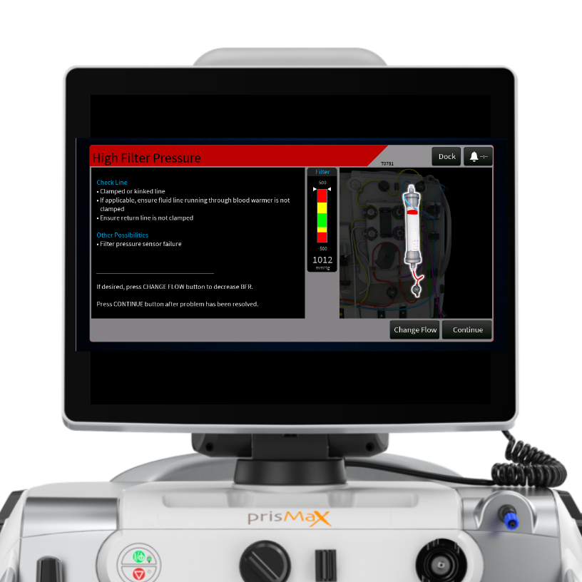
T0781 - High Filter Pressure
Alarm definition
The alarm indicates that the pressure in or across the hemofilter membrane is too high, which may indicate issues like filter clotting or incorrect system configurations.
Possible causes
- Clamped or kinked line
- Filter High pressure drop that would indicate the filter set is clotting or clotted
Operators Instruction
- Unkink lines
- Consider a decreased Blood Flow Rate (BFR)
- Change filter set - Tap the Discard Set button and change the set
Additional Information
- Max Pressure Drop is dependent on the filter in use
Once the issue is fixed, the ‘Continue’ button can be pushed.
T0782 – TMP Pressure Excessive
The alarm indicates that the pressure in or across the hemofilter membrane is too high, which may indicate issues like filter clotting or incorrect system configurations.
Possible causes
- High transmembrane pressure (TMP) due to a protein coating on the blood side of the membrane leading to a decrease in membrane permeability (clogging)
- Filter High pressure drop that would indicate the filter set is clotting or clotted
- Kinked lines
Operators Instruction
- Change filter set - Tap the Discard Set button and change the set
- Unkink lines
- Review anticoagulation
- Consider a decrease Blood Flow Rate (BFR)
Additional information
- Max TMP limit in CRRT filters is 300mmHg
- Max Pressure Drop is dependent on the filter in use

T0786 – Membrane pressure rising (CRRT)
The alarm indicates an increase in pressure across the system membrane.
Possible causes
- Clamped or kinked line
- Inadequate anticoagulation
- Air leak at filter or return pressure sensor
- High Rep, PBP, or PFR flow rate
- Too high blood flow rate
Operators Instruction
- Correct kinked or clamped lines
- Check for air leak at filter or return pressure sensor
- Consider decreasing PFR, Rep, or PBP flow rates
- Consider decreasing Blood Flow Rate
Additional information
- Assess anticoagulation requirements according to hospital policy
.jpg)
T2125 – Bag on wrong scale
Alarm definition
The alarm indicates indicates that the PrisMax has detected an unexpected weight change on the effluent scale.
Possible causes
- Unexpected weight on auto-effluent (AE) scale
- Effluent bag is on the wrong scale
- Object is hanging on the auto-effluent (AE) scale
Operators Instruction
- Confirm that nothing is hanging on or touching the auto-effluent (AE) scale
Once the issue is fixed, the ‘Continue’ button can be pushed.

T0823 – Flow Problem Caution Alarm Solution bag
(T0824, T0935, T1069, T1070)
Alarm definition
The alarms indicate that the solution bag is not emptying as expected.
(See screen to identify line)
Possible causes
- Solution line(s) is kinked, clamped, or connected to the wrong bag(s)
- Solution bag is touching another object, leaking, or hanging on the wrong scale
Operators Instruction
- Correct kinked or clamped lines
- Verify line connections
- Remove any object touching the bag
- Check the bag for leaks
- Verify that bag is hanging on correct scale
Additional information
- Multiple flow alarms contribute to the fluid loss/gain limit. Once the maximum fluid/loss limit is reached therapy is suspended and, the set must be replaced
Once the issue is fixed, the ‘Continue’ button can be pushed.

T0822 – Flow Problem Caution Alarm EFFLUENT bag
(T2161, T2160)
Alarm definition
These alarms indicate that the effluent bag is not filling or the AE set is not draining.
Possible causes
- Yellow effluent line is kinked, clamped, or connected to the wrong bag
- Effluent bag is touching another object, leaking, or hanging on the wrong scale
- If using AE set check AE bag for debris
Operators Instruction
- Correct kinked or clamped lines
- Verify line connections
- Remove any object touching the bag
- Check the bag for leaks. Change bag if needed
- Verify that bag is hanging on correct scale
Additional information
- Multiple flow alarms contribute to the fluid loss/gain limit. Once the maximum fluid/loss limit is reached therapy is suspended and, the set must be replaced
Once the issue is fixed, the ‘Continue’ button can be pushed.

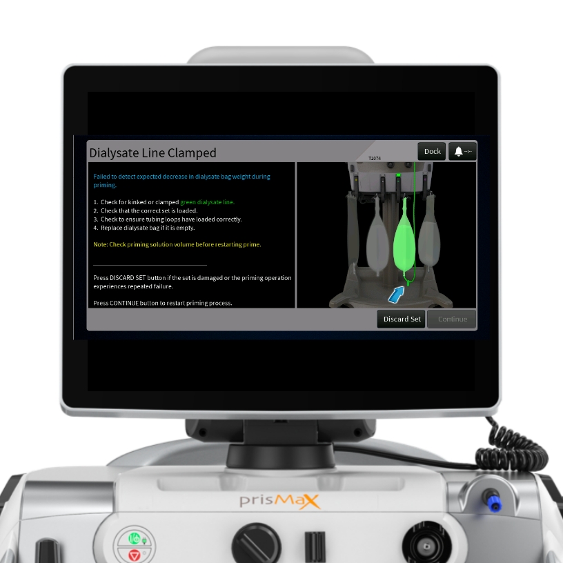
T1772, T1073, T1074, T1075 - Line Clamped Alarm
Alarm definition
The alarms indicate that a solution line is clamped or disconnected. (See screen to identify line)
Possible causes
- Line is clamped
- Line is disconnected
- Kinked or obstructed line
Other causes/Considerations
- If any of these alarms occurs in PRIME ensure above causes are eliminated
- If alarm persists in PRIME consider using a new set
Operators Instruction
- Verify that the lines are not kinked or clamped
- Ensure all connections are correct, including bags
- Ensure tubing loops are correctly loaded in the pump
- If the set is damaged, discard the set and replace it with a new one
Once the issue is fixed, the ‘Continue’ button can be pushed.
T2309 – Air detected in prime
Alarm definition
The alarm indicates that air has been detected in the return line during the priming sequence of the PrisMax.
Possible causes
- Air Presence: Actual air is present in the return line during priming
- Priming solution: The bag used for priming the system is depleted of fluid
Insufficient priming solution available at the end of the sequence
Other causes/Considerations
- Lower Liquid Level Sensor (LLS) might be erroneously enabled during the priming cycle
Operators Instruction
- Check priming bag – replace if necessary
- Check line connections - Ensure there is no air between the ABD and the patient end of the return line
- Reprime or discard the set
- If air continues discard the set
Additional information
- Clamp unused lines after priming is complete and before starting patient treatment. A saline bag may be hung on the PBP if not in use.

T0608 – Wrong set detected
Alarm definition
The alarm indicates that an incorrect set is loaded or that components are not properly secured during setup.
Possible causes
- Wrong set loaded
- Return pressure sensor line not connected
- Return line not in clamp
- Tubing segments or loops are not loaded correctly
- Pump segments not loaded properly into rotors and raceways
Operators Instruction
- Load correct set
- Check for correct loading of tubing segments or loops
- Check the return pressure sensor line connection and that the return line is properly placed in the return clamp
- Check for clamped or kinked Dialysate or Replacement lines
- Verify that pump segments are correctly positioned in the rotors and raceways
Software 3.5 edition
- If pump tubing segments or loops are not properly loaded tap Unload Set to unload the set. After the set unloads, tap on Load Set, to cause the set to be loaded again. Tap Retest to clear the alarm and retry set recognition test.

T1313 – Blood Leak Detector (BLD) normalization failed
Alarm definition
The alarm indicates a normalization failure in the BLD. This occurs when the system is unable to normalize the detector’s signal to a baseline value.
Possible causes
- Effluent line incorrectly installed
- Effluent Line Clamped
- Air bubbles in the effluent line
- Dirty effluent line
- Dirty BLD mirrors
Operators Instruction
- Check for clamped effluent line
- Slide the tubing back and forth in the Blood Leak Detector (BLD)
- Squeeze the air bubbles out of the return line
- Remove and clean the effluent line with an alcohol swab
- Clean BLD mirror with a lint-free cloth and isopropyl alcohol
Once the issue is fixed, the ‘Continue’ button can be pushed.

T0853 – Blood Leak Detector (BLD) normalization failed alarm in therapy
Alarm definition
The alarm indicates a normalization failure in the BLD during therapy. This occurs when the system is unable to normalize the detector’s signal to a baseline value.
Possible causes
- Tubing incorrectly installed in the BLD
- Tubing is cloudy or debris in the tubing path
- Air in the effluent line
- The wrong section of tubing is installed in the BLD
- Dirty BLD optics
- Blood is present in the effluent line
Operators Instruction
- Verify that effluent line is correctly installed in the BLD
- Remove air bubbles in effluent line
- Slide the tube inside the BLD to increase detection signal
Once the issue is fixed, the ‘Continue’ button can be pushed.

T2315 - Foam detected
Alarm definition
The alarm occurs when the PrisMax identifies the presence of foam in the deaeration chamber.
Possible causes
- Presence of foam in the deaeration chamber
- Foaming can be a result of an air leak in the set, it is important to inspect the set for leaks, especially at joints on the access line
Other causes/Considerations
- If the foam reaches the fluid barrier, it can interfere with the return pressure monitoring and cause alarms
Operators Instruction
- Increasing the post-replacement infusion rate may reduce the amount of foam
- Tap the Override button to disable automatic liquid levelling
- If the override button is cleared, automatic levelling of fluid in the chamber will resume
T0830 - Blood Leak detected
Alarm definition
The alarm indicates that the PrisMax has detected the potential presence of blood in the effluent line, indicating a possible blood leak e.g. caused by a ruptured filter membrane.
Possible causes
- Leak in filter membrane
- Tubing incorrectly installed in the Blood Leak Detector (BLD)
- Tubing is cloudy or debris in the tubing path
- Air in the effluent line
- The wrong section of tubing is installed in the Blood Leak Detector (BLD)
- Dirty Blood Leak Detector optics
Operators Instruction
- Check for kinked effluent line
- Check for air bubbles in effluent line in the Blood Leak Detector
- Verify that effluent line is correctly installed in the Blood Leak Detector (BLD)
- Check for liquid or debris in the Blood Leak Detector (BLD) tubing path and effluent line: clean with a lint-free cloth, then dry thoroughly
Additional information
If air bubbles recur, check for kinked effluent line, or decrease Blood Flow Rate (BFR). If blood is in the effluent line, change the set. Send sample of effluent to the blood lab for cell count. Patient disease state may cause effluent discoloration, indicating removed free hemoglobin, rather than a blood leak in the filter membrane. Press Override and send effluent sample to blood lab for a cell count. If the result confirms blood cell presence, change the set. Once the issue is fixed, the ‘Continue’ button can be pushed. Tap the Continue button to clear the alarm and return to normal operations if no blood present. Follow Hospital policy and procedure.

T0792 – Air detected in blood
Alarm definition
If the deaeration chamber cannot remove all the air from the return line before air reaches the Air Bubble Detector (ABD), the system stops all pumps, warns of air in blood, andcloses the return clamp.
Possible causes
- Leaking or disconnected catheter
- Air entry from a bag, blood warmer, syringe line, access or PBP lines
- Set not fully primed
Operators Instruction
- Reposition the catheter according to hospital protocol
- Inspect the entire set for leaks or disconnections
Additional information
If air is present in the entire return line – change set.
If air is still present in the chamber after following the on-screen instructions or if the alarm reoccurs, dock the alarm, and continue with the manual air removal.
Required equipment:
- Sterilized syringe with 21-gauge (or smaller diameter) needle.
Follow these steps to remove air from blood manually:
- Clean the blue sample site on the return line
- Insert a 21-gauge (or smaller diameter) needle with syringe into the blue sample site (return line)
- Aspirate air/blood until the return pressure reaches a negative value (0 to -100 mmHg)
- Remove the needle
- Tap the Open Clamp button to remove air and draw blood from patient into the return line/deaeration chamber
- Verify that the alarm stops and the return line clamp opens. Air in the return line is drawn into the chamber and automatically eliminated from the set through the return pressure port. Blood is also drawn from the patient into the return line and deaeration chamber

T2281 - Bag not detected during prime
Alarm definition
The alarm is triggered when the Thermax Blood Warmer disposable bag is not detected during the priming phase.
Possible causes
- Warmer disposable not detected
Operators Instruction
- Ensure the bag is inserted smoothly and not rolling or getting caught upon insertion
- Confirm that the warmer disposable is pushed in all the way
- Ensure lock is fully functional and closed
- No cleaning residue or condensation on the heating plates end LEDs. If present dry and remove using approved cleaning materials
- Cancel prime and reload the warmer disposable
Additional Information
- If above steps have been completed and still unable to progress send to Biomedical engineering
Once the issue is fixed, the ‘Continue’ button can be pushed.

T2284 - Bag not detected during therapy
Alarm definition
This alarm is triggered when the blood warmer disposable bag is not detected during therapy.
Possible causes
- Warmer disposable not detected
Other causes/Considerations
- Do not open the blood warmer or unlock the bag during treatment
Operators Instruction
- Confirm that the warmer disposable is pushed in all the way
- Do not open the blood warmer or unlock the bag during treatment
- Tap the Discard Set button and change the set. Discontinue therapy if this cannot be resolved

Connecting disposable sets
Get an overview of the principles behind the disposable filter set and how it is connected to the PrisMax machine.

The lines
- PBP LINE (WHITE-STRIPED)
This line carries prescribed infusion solution from the bag on the PBP scale to the blood access line. If citrate anticoagulation is in use, the PBP line carries the citrate solution. - REPLACEMENT LINE (PURPLE-STRIPED)
Carries replacement solution from the bag on the replacement scale to the blood-flow path. This line is not used in all therapies. - DIALYSATE/REPLACEMENT 2 LINE (GREEN-STRIPED)
Unique to CRRT sets, this line carries solution from the green scale to the fluid compartment of the filter (for dialysate) or to the blood flow path (for replacement 2). - EFFLUENT LINE (YELLOW-STRIPED)
Transports ultrafiltrate and waste dialysate from the filter’s fluid compartment to the effluent bag. - ACCESS LINE (RED-STRIPED)
Carries blood from the blood access to the filter. - RETURN LINE (BLUE-STRIPED)
Carries blood from the filter back to the patient. - SYRINGE LINE
Used for systemic anticoagulation, this line carries anticoagulant from the syringe to the blood flow path. For regional anticoagulation*, it carries calcium to the patient connection. It includes a non-return valve to prevent blood from diffusing into the syringe line.
*not approved for use in some countries

Sample sites & pressure pods
- SAMPLE SITES
Color-coded ports that allow for needle entry to obtain fluid or blood samples. These accommodate a 21-gauge or smaller diameter needle attached to a syringe. - PRESSURE PODS
Three circular pods (access, filter, and effluent) that contain a diaphragm and fit into a pressure sensor housing on the control unit, enabling non-invasive pressure monitoring.

Filter & deaeration chamber
- FILTER
Characteristics of the filter vary according to the disposable set used. Specific details are provided in therapy descriptions. - DEAERATION CHAMBER
Positioned on the return line, it allows the system to manage air and add post-filter replacement solution to the return line (Blue-Striped). - CHAMBER MONITOR LINE
Connects the deaeration chamber to the return pressure port, enabling pressure monitoring and air removal. It includes a fluid barrier to protect against contamination.

Cartridge & pump segments & discharger ring
- CARTRIDGE
The plastic component of the disposable set, containing tubing segments for the pumps and pinch valves. It covers the fluid and blood pumps when installed and facilitates automatic set loading/unloading. - PUMP SEGMENTS
Tubing lengths that fit into the raceway of each pump (blood, PBP, dialysate, replacement, and effluent). They are automatically loaded when the cartridge is installed to the loader on the front panel. - ELECTROSTATIC DISCHARGER RING
Discharges electrostatic voltage from the set, which can cause artifacts cardiac monitors.

Barcode
Scan the unique barcode to secure a match between the filter set and the set type selected in the SETUP menu on the PrisMax.

Unpacked set
The filter set contains the filter membrane, filter casing and all required connections.
Disposable set lines and connections correspond to ports, clamps, pumps, and associated scales, and they are color-coded to facilitate intuitive connection.
.png)
Filter set connected

On-screen installation instructions
Once the filter set is attached, onscreen step-by-step instructions will guide the connection of the components.
Tap the corresponding blue circle to access additional information on the specific connection.

Connect components
When all components of the set are connected, tap ‘Load Set’ to load set.

How to power up the machine
- ATTACH THE AC POWER CORD TO AN AC POWER SOURCE
(Power cords are country-specific) - TO POWER ON THE CONTROL UNIT, PRESS THE GREEN ON/STANDBY BUTTON ON THE FRONT PANEL
- THE CONTROL UNIT POWERS UP AND THE START SCREEN APPEARS

How to power up the machine
ON/STANDBY BUTTON
Turns the PrisMax system on or places it in standby. When the system is on, the display and all electronics are on. Press and hold to enter standby. When the system is in standby, all electronics are off, except for power supply and battery charging.
POWER INDICATOR (GREEN)
Alternating current (AC) or battery power connected to the system. On: system running on AC. Off: no AC. Flashing: running on battery or battery charging during standby mode.
STOP BUTTON
Stops all motors and closes the return clamp. This provides an independent way to stop the device if the screen fails.
STOP INDICATOR (YELLOW)
Control unit is stopped (all pumps stopped).

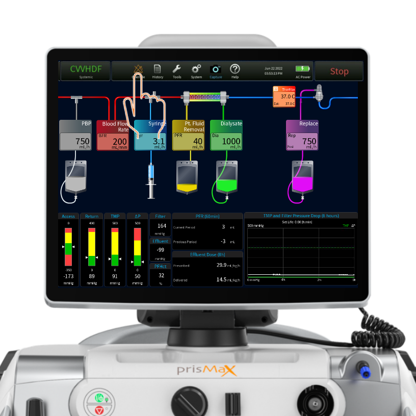
The operations screen
The operations screen is the home screen during therapy.
Tap or press the touch-screen to access and operate tools and functions.
- TOOLBAR
- MAIN SCREEN - FLOW RATES / FILTER & BAG SETUP (INCLUDING THERMAX)
- OPERATION PARAMETERS

Toolbar - Therapy mode
- Shows selected treatment modality and anti-coagulant mode
- Tap to bring up current prescription for review
- Tap PATIENT to change patient weight and hematocrit
- Button modes: SETUP, THERAPY TYPE & END

Toolbar - Alarm
The toolbar can include the following options - but not all buttons appear in all situations.
Override – to turn off. Depending on the type of alarm/type of severity.
|
This is shown if an active alarm is minimized/docked.
|
 |
|
This is shown if an alarm is overridden or turned off.
|
 |
Toolbar - History
Tap HISTORY to access the HISTORY screen. Active during THERAPY or END mode.

Toolbar - History
Tap/Press to access:
- Prescription – to view prescription history
- Dose – to view dose delivery; percentage delivered and in DAILY, LAST 24 Hrs. and TOTAL intervals
- PFR – Patient Fluid Removal overview in intervals: 1 Hr., 8 Hrs., 24 Hrs. and TOTAL
- Events – Event log; overview of all auto-logged events since onset; time-stamped. Events can be sorted by event types
- Pressures – Pressure graph; view pressure levels over time (trends). Select one or more pumps to populate the graph
- Temperatures – Temperature graphs: view temperature levels over time; select one or more TherMax temperature sensors to populate graph

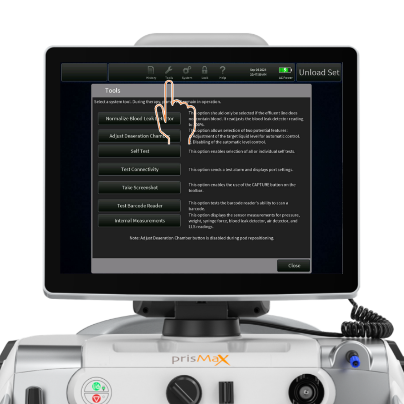
Toolbar - Tools
Tap the icon to access the TOOLS menu.
Provides access to tools for handling selected issues
- Select tool by tapping
- Instructions available for all tools
Toolbar - System configuration
- Display – set and adjust brightness and status light mode
- Sound – set and adjust volume for non-essential alarms
- System info – selected information about the device; maintenance data, software version, serial number and enabled accessories on the machine
- USB import/export – service screen for USB port options

Toolbar - Lock

Toolbar - Help
Tap the icon to access selected topics and relevant information.
- Abbreviations
- Buttons
- Symbols
- Therapies
- Setup
- Run Mode
- Maintenance

Toolbar - Date/time/power
Shows current date and time.
Shows power source (AC or battery) and battery level.
The button changes title and function depending on the operating mode
STOP
END
CANCEL
In THERAPY mode the STOP button stops all motors and closes the RETURN CLAMP

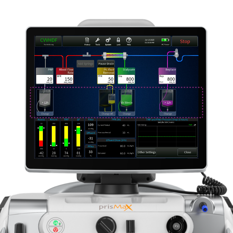
Main screen - Bag status
Press the BLUE area on the screen to bring up schematics of the fluid bags.
If using the Auto Effluent set, it can be changed during therapy by selecting the Change AE set option.
It shows the time left on each bag change before a change is needed in hours and as minutes left when there is less than one hour remaining.
Press/Click on relevant bag icon for the CHANGE BAG instruction screen.
Main screen - TherMax
View current temperature set for the TherMax blood warmer.
Press/tap the TherMax box to enable and disable the blood warmer and to adjust the temperature.

Operation parameters
The operation parameters section is built up around 5 sections:
- PRESSURE BARS
Displays pressure bars, ACCESS, RETURN, ΔP (filter pressure drop) TMP (transmembrane pressure). The pressure bars indicate the current pressure measurement level (white arrows), operating range, and alarm limits, including numeric pressure levels displayed. - SINGLE DATA
Single data: FILTER (filter pressure), EFFLUENT (effluent pressure) = calculated values from Pressure Bars. PFHct (post filter hematocrit). - EFFLUENT DOSE
Shows prescription value and what has been delivered (for more detailed view = HISTORY). - PFR (PATIENT FLUID REMOVAL)
Volume of fluid removed from the patient (for more detailed view = HISTORY). - PRESSURE HISTORY GRAPH
Displays the filter drop pressure and the TMP/TMPa (as applicable) pressure over the last 6 hours of treatment and current set life (hr:min). Also shows the set life.

Pressure bars
Pressures are displayed in the form of pressure bars and numerics.
The pressure bars indicate the current pressure measurement, operating range, and alarm limits. The therapy in use determines which pressure bars are displayed.

Pressure bars - schematics
Pressures are displayed in a form showing the normal operating range (green), advisory pressure levels (yellow), and warning limit levels (red).
White arrows indicate the current level.
A numeric pressure level is also displayed.
Pressure bars are grey when operating ranges are being established and during self-tests.
The operations screen displays data that is monitored during treatment.

Pressure bars - operating point
During therapy, the software stores a reference pressure value for each pressure, called the pressure operating point. The machine continually compares the current pressure at each monitoring site with the reference value to sense changing pressure conditions.
Pressure operating points are first set shortly after treatment begins.
To maintain pressure monitoring accuracy during treatment, the machine
updates pressure operating points after any of the following happens:
- Blood flow rate change
- Blood pump restart
- Alarm reset
- Self-test

Pressure bars - functionality
ACCESS and RETURN pressure (green state)
Normal access pressure can be negative or positive, depending on the access connection. Normal return pressure is nominally positive.
The normal access and return operating range is set from the operating point:
For blood flows of <200 mL/min, the operating point is ±50 mmHg; for blood flows of >200 mL/min or more, the operating point is ±70 mmHg from the calculated pressure point. If the operating value (white arrows) stays within the “green” range, the therapy will run with no alarms
ACCESS and RETURN pressure (yellow and red state)
When the operating pressures move outside the normal operating ranges (green) an alarm will be triggered to notify the operator.
An advisory or caution alarm is declared for the “yellow” advisory pressure range.
A warning alarm is declared for the “red” pressure range.

Pressure bars - functionality
CRRT: TMP (transmembrane pressure) ΔP (filter pressure drop)
TPE: TMPa (access transmembrane pressure) ΔP (filter pressure drop)
The machine uses the pressure data to calculate ΔP, TMP, or TMPa.
ΔP is calculated to determine the pressure conditions in the filter blood compartment as blood moves through the filter.
TMP (CRRT) is the applied pressure across the filter membrane during operation and shows the pressure difference between the blood and fluid compartments.
TMPa (TPE) is the pressure difference between the blood and fluid compartments at the inlet side of the filter.
The device, set, and therapy type will determine the default pressure alarm limits.
ΔP, TMP, and TMPa pressures (green state)
The filter operates within the normal parameters set for the filter in use.
ΔP, TMP, and TMPa pressures (yellow and red state)
As the pressures trend or move towards the “yellow” or “red” regions, these calculated pressures are used to notify about clotting or membrane pore plugging (clogging) in the filter and, if extensive enough, notify that a change of set is required.

The back panel elements
- ETHERNET CONNECTOR
- SERIAL PORTS
Connections for data exchange - USB PORT
- WIFI ANTENNA CONNECTOR
Enabling WIFI connectivity (optional for TrueVue connectivity) - REMOTE ALARM CONNECTOR
To connect to the call-light system or alarm system of the hospital - HAND CRANK
Allows manual pump operation to return blood to the patient or to turn fluid pumps. For emergency situations only - POWER SOCKET
A/C power connection - SERIAL NUMBER
Unique serial number of the machine
